Arduino Project: LDR
In this project you use an LDR to switch lights on or off, depending on whether there is more or less light shining.
For this project we will use a LDR. LDR is an abbreviation for light depending resistor. Which means that the resistance depends on the amount of light shining on it. The more light shines on the LDR, the lower the resistance becomes.
We can read a value from the LDR with the Arduino. In this project we attach different values to the LED lights. We do this in such a way that if more light shines on it, more LED lights will light up. We do this with if else logic gates and the analogread function. In the programming section I explain what these functions mean.
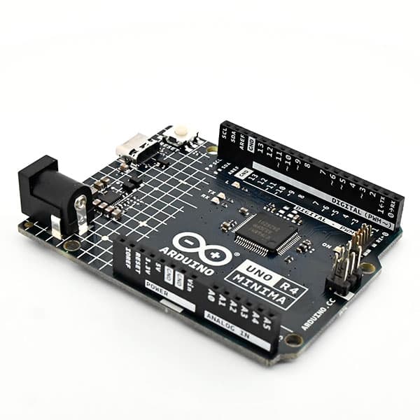
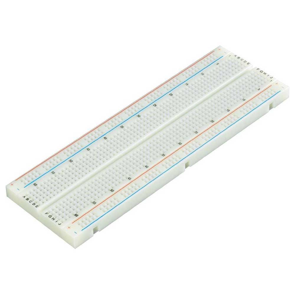
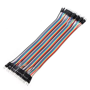
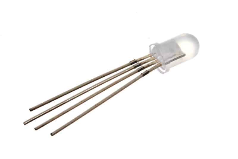
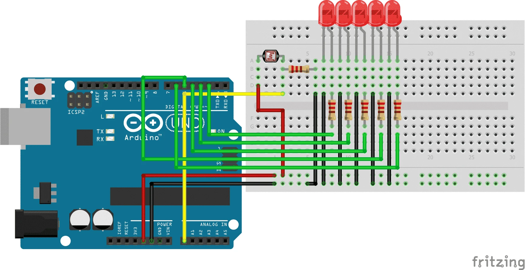
Building and Wiring
Programming
Once you have connected everything correctly, you can start programming.
The code for this project is quite short. In the code we use the analogread function and if else logic gates .
We use the analogread function to read the value of the analog pin. This is the value of the LDR. Then we use the if else logic gates.
At the moment the value matches (so if is) the light goes on for us. If the value does not match (so else is) the light does not light.
//hier zetten we alle componenten op een pin
int sensor = A0;
int led1 = 2;
int led2 = 3;
int led3 = 4;
int led4 = 5;
int led5 = 6;
int Value = 0;

void setup(){
  //hier zorgen we dat die pinnen een puls geven
  pinMode(led1, OUTPUT);
  pinMode(led2, OUTPUT);
  pinMode(led3, OUTPUT);
  pinMode(led4, OUTPUT);
  pinMode(led5, OUTPUT);
}

void loop(){
  //nu zorgen we ervoor dat hij A0 leest
  Value = analogRead(sensor);
  delay(100);
  //nu laten we het lampje aangaan
  //als de waarde 110 of hoger is
  if(Value >= 110){
    digitalWrite(led1, HIGH);
  }else{
    //anders gaat hij uit
    digitalWrite(led1, LOW);
  }
  if(Value >= 125){
    digitalWrite(led2, HIGH);
  }else{
    digitalWrite(led2, LOW);
  }
  if(Value >= 140){
    digitalWrite(led3, HIGH);
  }else{
    digitalWrite(led3, LOW);
  }
  if(Value >= 155){
    digitalWrite(led4, HIGH);
  }else{
    digitalWrite(led4, LOW);
  }
  if(Value >= 170){
    digitalWrite(led5, HIGH);
  }else{
    digitalWrite(led5, LOW);
  }
}