4.7 avg.
5428+ reviews5428+ reviews
Order by 16:00 for same day shipping
14 days return
DE
EN
Individual
Business
Arduino Project: DS18B20 Thermometer
In this project you will learn how to make a thermometer with an Arduino. The temperatures that are measured will show you on a seven segment screen. As a sensor we use a DS18B20 temperature sensor. For the seven segment screen we use a 2-digit 7-segment LED red.
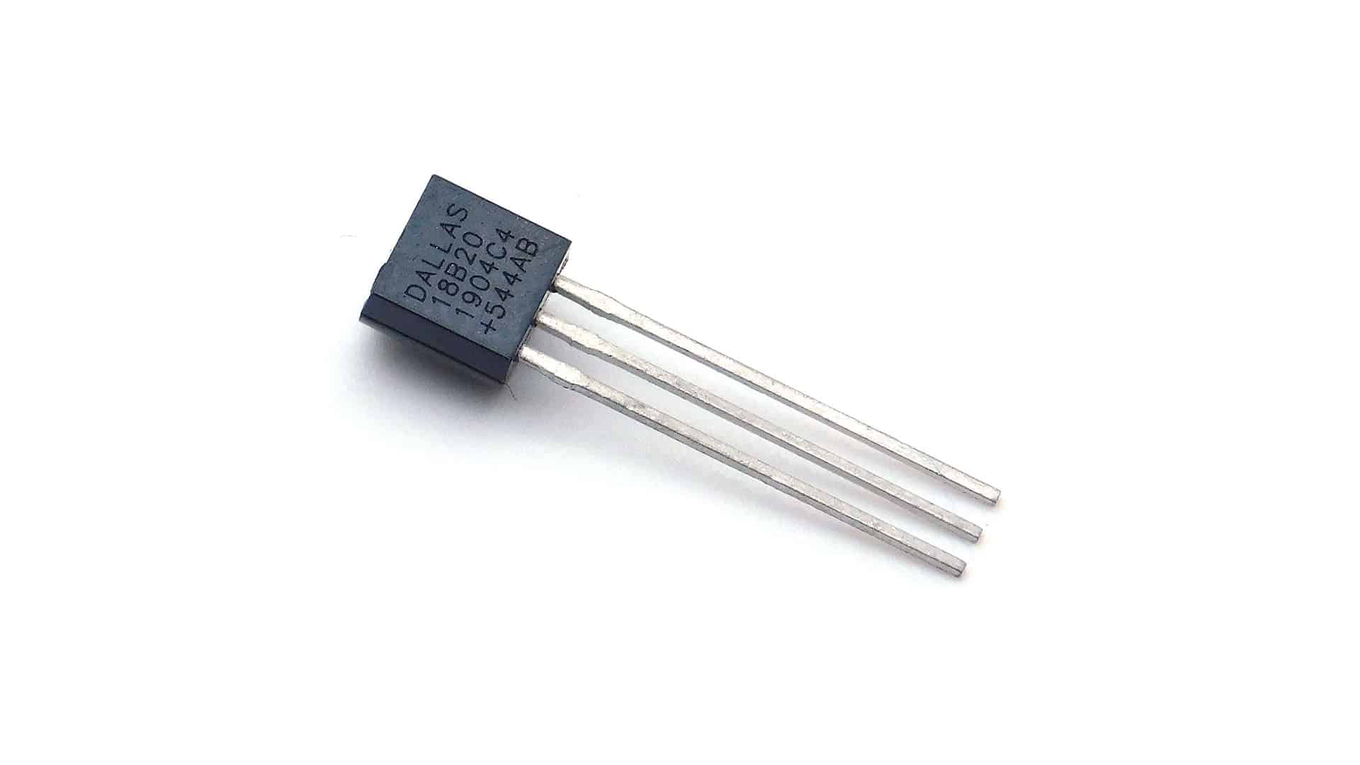
DS18B20 temperature sensor
The DS18B20 is a digital temperature sensor. It communicates easily with an Arduino through one data pin. The left pin of the sensor must be connected to GND (-). The middle pin is connected to an analog data pin and the right one is connected to VCC (5v). The DS18B20 is available in a waterproof and a non-protected version. The waterproof version is often used in liquids or humid areas. The “bare” sensor is often used for measuring the outside temperature.
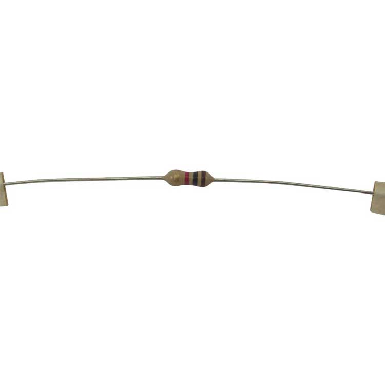
The DS18B20 can measure temperatures between -55 and 125 degrees Celsius. With an accuracy of 0.5 between -10 and 85. It is not recommended to expose the sensor to temperatures above 100 degrees Celsius. In principle, only the GND and the data pin are required to use this sensor. However, the values are then so low that they cannot be read. To make the values higher, a "step-up" resistor must be used. In the case of this sensor, this is a 4.7K Ohm resistor that is placed between the VCC and the data connection.
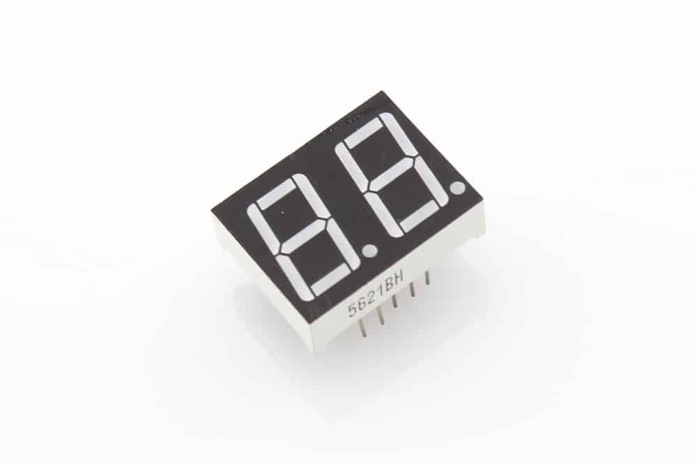
2-digit 7-segment LED red
A 7-segment display comes in many different shapes and sizes. For this project we use one with 2 digits and 18 connection pins. The layout of the pins is shown in the image below. In this project we do not use the DP connections. As you can see in the image below each "bar" has its own letter(s). In this project there is no room for your own input when connecting the display. If the order is not the same the coding will not work properly.
The display can get quite warm after long use. This is not a problem below 80 degrees Celsius.
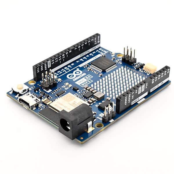
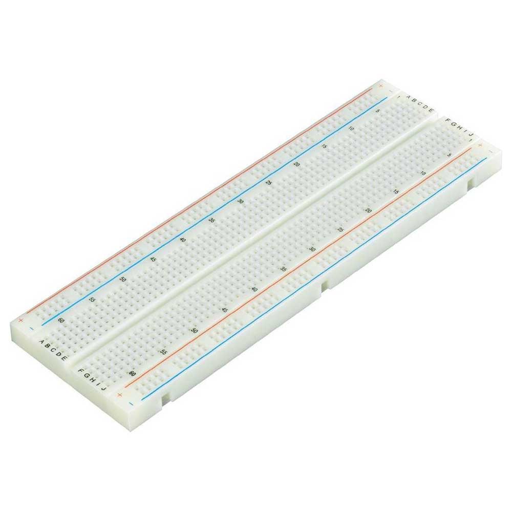
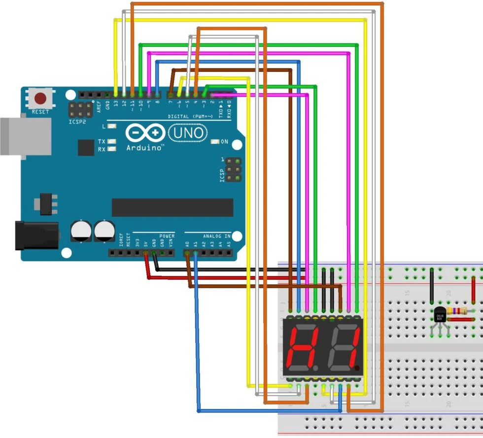
Building and Wiring
Now that you have all the components you can start connecting the components. Below you see a drawing of how to connect the components to the Breadboard and the Arduino. Be careful to connect the DS18B20 correctly, if you connect it the wrong way around the sensor can break. The sensor has a flat and a convex side. The flat side is the front. The ground pin is then on the left side.
Programming
Most lines of coding are spent on the 7-segment display. This needs a lot of coding because there is no simple library for it. In addition, the coding consists of some standard lines and the reading of the sensor.
In the beginning we make sure that everything is set up properly. You have to add the libraries for the sensor. Then indicate on which pin the data comes in. Then you enter that data in the libraries. Now we come to the part of the 7-segment display. We create an array. In this array we have to indicate how many digits we are going to add, in this case 10 (0-90. We also have to indicate how many values there are per digit. Then you are going to indicate the data per digit, you do this by means of HIGH or LOW. The 7 values that you are going to give represent the 7 segments in the display (a, b, c, d, e, f, g). If a segment is set to HIGH, that segment will light up.
Once you have done all this we still need to make sure that we can operate the numbers separately. We will do this by creating a 3rd and 4th void. We need to call these voids at the beginning. Now that all the preparation is done we go to the setup. Here we start the sensor and the serial communication. Then we indicate which pins are input and which are output, here pin 14 and 15 are analog pin A0 and A1.
Next we can start with the main coding. First we ask the sensor for the values it measures. Then we add these values to a variable. This value is a number with two digits after the decimal point. This is a problem because we can only show 2 digits. For the first digit (D1) we have to divide the value by 10 and then take the first digit before the decimal point. For the second digit (D2) we use the normal value and take the first digit before the decimal point. For example, with a value of 23.45 you would get 2 on D1 and 3 on D2. Then we still have to translate these digits so that the correct segments light up. We do this by referring to the 3rd and 4th void where we will do this translation. Finally, within the large coding we write the temperature on the serial monitor.
For the 3rd and 4th void the same coding is used only a different start pin. For this coding to work it is important that the at/mg of a digit are also connected after each other. So from D1 a is on pin 2 and g on pin 8. This way you can just add 1 to the variable for the pin to go to the next segment.
To start the void by indicating where the a of that number is connected. Then we create a for loop that plays itself a total of 7 times. This is so that you go through all the segments and all the values that need to be entered. In this loop we start by telling it what to do with the first pin. By referring to the array. Every time this void is repeated, 1 is added to the pin so it goes to the next segment.
This works the same for the 4th void. Only then it has a different start pin.
/*
   Deze code gaan we gebruiken voor het programmeren van een thermometer.
   De temperatuur gaan je laten zien op een 2-digit 7-segment Led.
   Deze temperatuur wordt in graden celcius weergegeven.

   Kijk op https://elektronicavoorjou.nl/arduino-info/arduino-projecten/ voor meer projecten met Arduino.
*/

// Deze twee library's zijn voor de temperatuur sensor.
#include <OneWire.h>
#include <DallasTemperature.h>

// Hier geven we aan dat de temperatuur sensor op A2 zit aangesloten.
#define DATA A2

// Hier geven we de nodige data aan de library's om van de data graden celcius te maken.
OneWire Data(DATA);
DallasTemperature sensor(&Data);

// Hier maken we een array aan voor de cijfer van de display.
int bcd_array[10] [7] =
{ //{A, B, C, D, e, f, g, dp},
  { HIGH, HIGH, HIGH, HIGH, HIGH, HIGH, LOW},     // 0
  { LOW, HIGH, HIGH, LOW, LOW, LOW, LOW},         // 1
  { HIGH, HIGH, LOW, HIGH, HIGH, LOW, HIGH},      // 2
  { HIGH, HIGH, HIGH, HIGH, LOW, LOW, HIGH},      // 3
  { LOW, HIGH, HIGH, LOW, LOW, HIGH, HIGH},       // 4
  { HIGH, LOW, HIGH, HIGH, LOW, HIGH, HIGH},      // 5
  { HIGH, LOW, HIGH, HIGH, HIGH, HIGH, HIGH},     // 6
  { HIGH, HIGH, HIGH, LOW, LOW, LOW, LOW},        // 7
  { HIGH, HIGH, HIGH, HIGH, HIGH, HIGH, HIGH},    // 8
  { HIGH, HIGH, HIGH, HIGH, LOW, HIGH, HIGH}      // 9
};

// Hier verwijzen we naar de 3de en 4de void die we hebben aangemaakt voor het schrijven op het 7-segment display.
void BCD0(int);
void BCD1(int);

void setup()
{
  // Aanzetten van de sensor.
  sensor.begin();

  // Seriële communicatie starten.
  Serial.begin(9600);

  // Alle inputs en outputs aangeven.
  pinMode(2, OUTPUT);
  pinMode(3, OUTPUT);
  pinMode(4, OUTPUT);
  pinMode(5, OUTPUT);
  pinMode(6, OUTPUT);
  pinMode(7, OUTPUT);
  pinMode(8, OUTPUT);
  pinMode(A2, INPUT);
  pinMode(9, OUTPUT);
  pinMode(10, OUTPUT);
  pinMode(11, OUTPUT);
  pinMode(12, OUTPUT);
  pinMode(13, OUTPUT);
  pinMode(14, OUTPUT);
  pinMode(15, OUTPUT);
}

void loop()
{
  // Waardes van sensor vragen.
  sensor.requestTemperatures();

  // Waarde aan variabel geven.
  int temp = sensor.getTempCByIndex(0);

  // Zorgen dan van 23 de 2 op het eerste cijfer komt en 3 op de tweede.
  int D1 = (temp / 10) % 10;
  int D2 = temp % 10;

  delay(1000);

  // Verwijzen naar de 3de en 4de void.
  BCD0(D1);
  BCD1(D2);

  // Temperatuur schrijven op Seriële monitor.
  Serial.println(temp);
}

// 3de void
void BCD0(int number)
{
  // Aangeven op welke pin de D1 (a) staat.
  int pin = 2;

  // Begin bij digitale pin 2 en tel elke keer 1 op. Tot en met dat je bij de 6de pin komt.
  // Elke herhaling gaat hij 1 stapje verder in de array.
  for (int j = 0; j <= 6; j++)
  {
    // Led in display aanzetten op de hiervoor aangegeven pin. Wel of niet aan ligt aan de array.
    digitalWrite(pin, bcd_array[number][j]);
    pin++;
  }
}

// Zelfde als BCD0 maar dan voor het 2de cijfer.
void BCD1(int number)
{
  int pin = 9;
  for (int j = 0; j <= 6; j++)
  {
    digitalWrite(pin, bcd_array[number][j]);
    pin++;
  }
}