4.7 avg.
5116+ reviews5116+ reviews
Order by 16:00 for same day shipping
14 days return
GB
EN
Individual
Business
Getting Started with the Raspberry Pi GPIO Kit
Introduction
The Raspberry Pi 's GPIO pins provide a powerful way to control external hardware, such as LEDs, sensors, and motors, and receive data from these devices. In this project, you will learn how to:
- How to configure a Raspberry Pi for GPIO use.
- How to connect hardware to the Raspberry Pi using the included kit.
- How to write simple Python programs in the Thonny IDE.
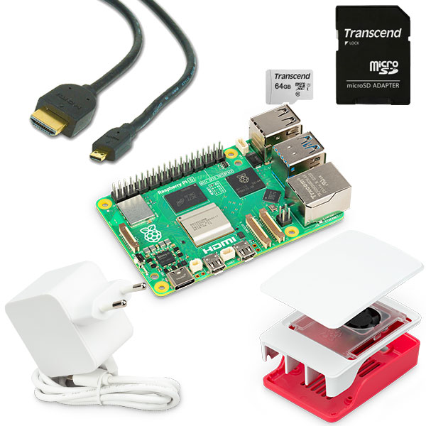
Step 1: Install Raspberry Pi OS
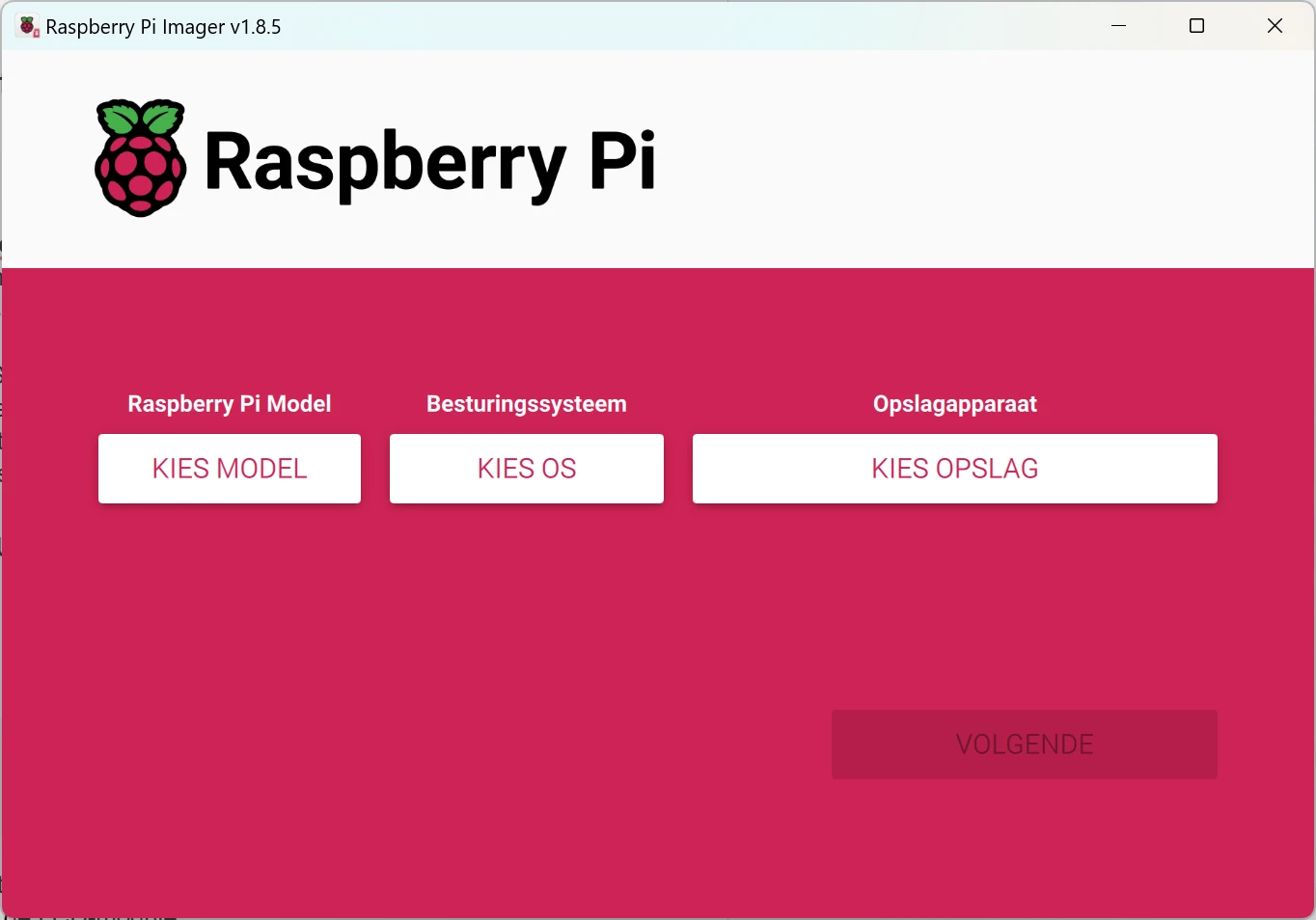
If your Raspberry Pi isn't set up yet, you can install the operating system using Raspberry Pi Imager :
- Download the Raspberry Pi Imager from raspberry pi.com.
- Insert the microSD card into your computer.
- Launch Raspberry Pi Imager and choose:
- Select Model: Raspberry pi (your model)
- Choose OS : Raspberry Pi OS (64-bit).
- Select Storage : Select the microSD card.
- Click Write and wait for the process to complete.
- Insert the MicroSD card into the Raspberry Pi and connect all cables.
Step 2: Configure Raspberry Pi
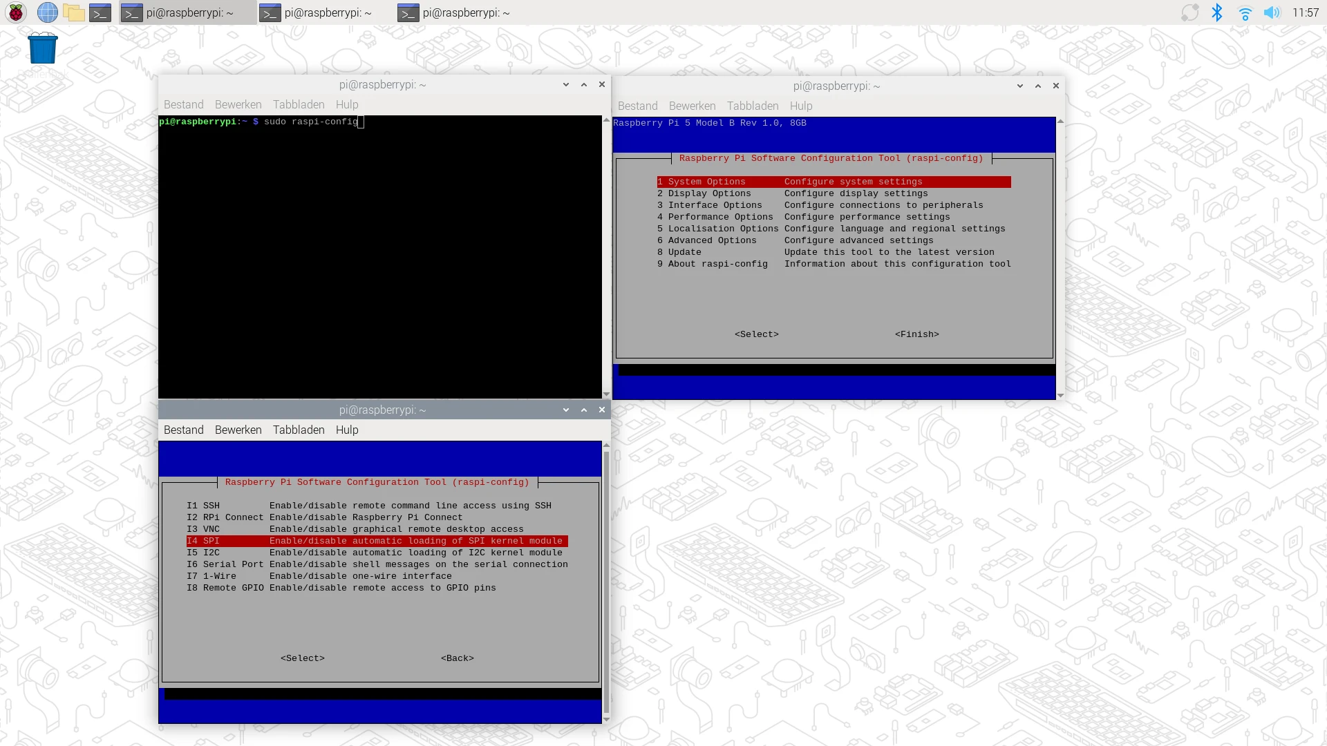
After booting the Raspberry Pi :
Open the LXTerminal :
sudo raspi-config
- Go to Interface Options and enable the following features:
- I2C : For devices such as the LCD module.
- SPI : For sensors and other modules.
- 1-Wire : For the DS18B20 temperature sensor.
- Save the changes and reboot the Raspberry
Step 3: Thonny Python IDE Explanation
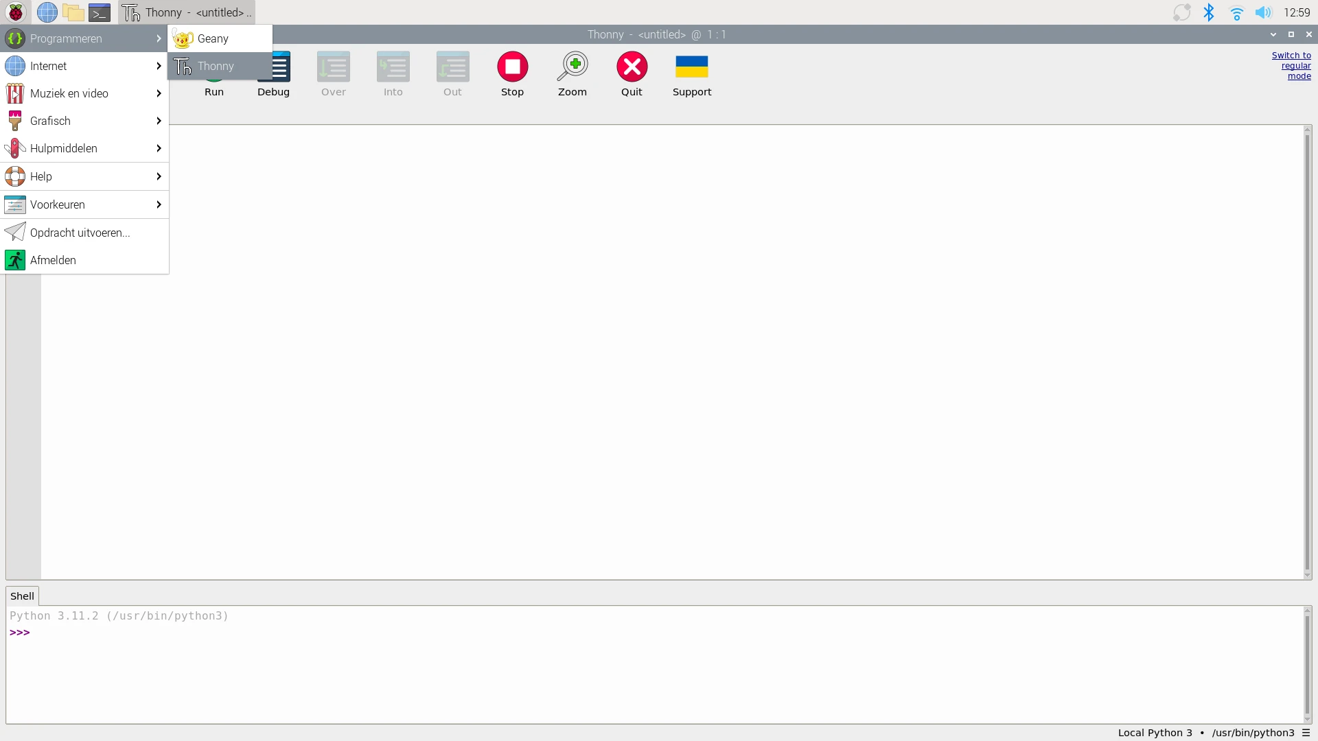
- Open Thonny :
- Click on the Raspberry Pi menu > Programming > Thonny Python IDE .
- Writing a script :
- Click on New File .
- Enter a simple print command such as:
print("Hallo, Raspberry Pi!")- Click Save and choose a name like test.py .
- To run the script :
- Click the green Run button (▶).
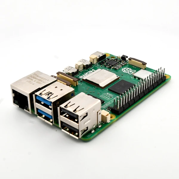
Step 4: GPIO Pins and Pinout Explanation
The Raspberry Pi has 40 GPIO pins that you can use for input and output. Here is a list of the most commonly used pins:
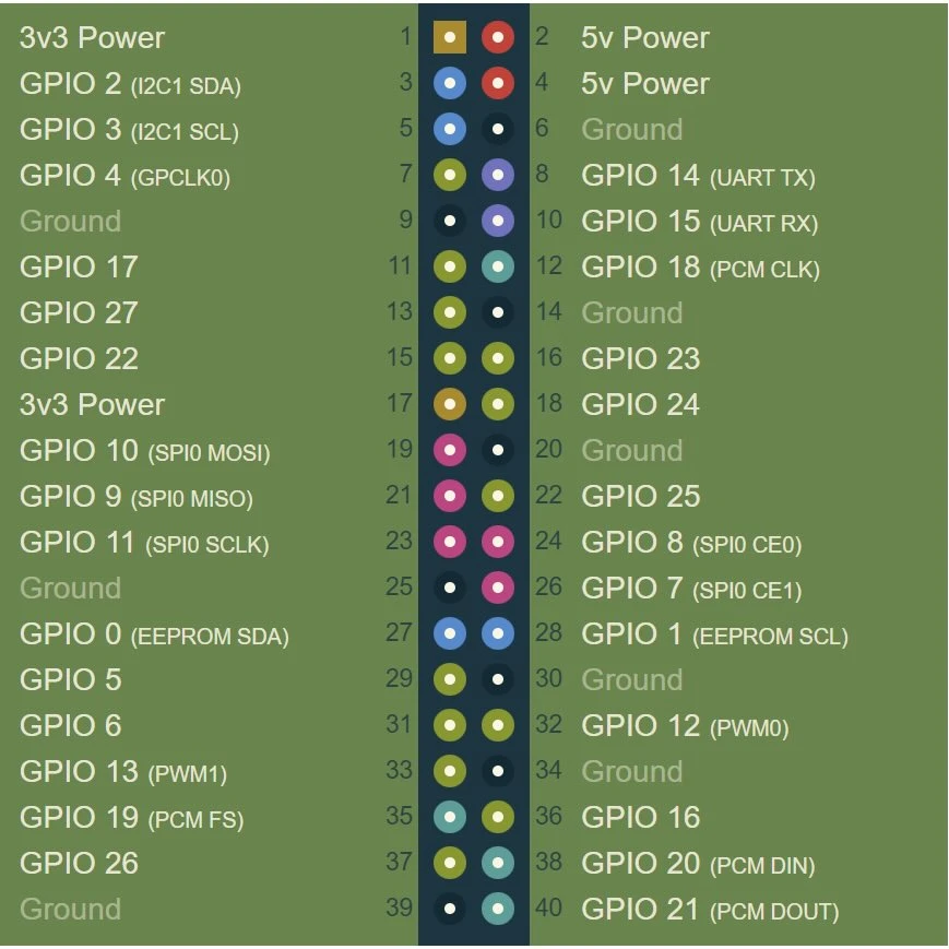
A detailed pinout diagram can be found at pinout.xyz .
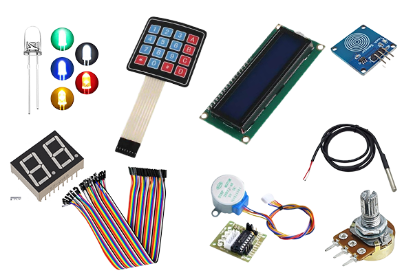
Step 5: Kit Explanation
The GPIO Kit contains a wide range of components that will allow you to perform various electronics and programming projects. Here is an overview:
What's in the GPIO Kit?
The GPIO Kit contains a wide range of components that will allow you to perform various electronics and programming projects. Here is an overview:
- Breadboard : Useful for building simple circuits without soldering.
- Jumper wires : Wires to connect components to the breadboard and the Raspberry Pi .
- LEDs : Visual signals; including an RGB LED to create colors.
- Resistors : For limiting current in circuits and protecting components.
- Pushbuttons : For use as input devices in circuits.
- LDR (light sensor) : Sensor that measures light intensity.
- Potentiometer : Variable resistor that can be used for various applications.
- Passive piezo buzzer : Sound source for creating tones or signals.
- Ultrasonic Distance Sensor (HC-SR04) : Measure the distance between the sensor and an object using ultrasonic sound.
- 2-Digit 7-segment display : For easy display of numbers.
- IR Remote Kit: For infrared wireless communication, such as remote controls.
- LM393 Sound Sensor : Measures sound intensity in the environment.
- Touch Sensor: Measures touches and can replace a push button.
- 4x4 Keypad : For easy entry of numbers and codes.
- Tilt Sensor (SW-520D) : Detects tilts or movements.
- 40-pin male/male header : For expanding and customizing your project.
- DS18B20 Temperature Sensor : Precision sensor for temperature measurements.
- Servo and stepper motor: Suitable for performing precise movements and rotations.
- 16x2 LCD display (I2C) : For displaying text or data, such as sensor values.
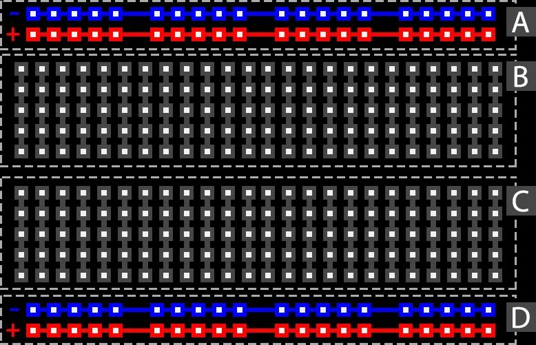
How does the breadboard work?
- Horizontal rows are connected in the middle (for components).
- Vertical rows (on the side) are usually for power and ground.
Result
After completing this project:
- Understand how the GPIO Kit works.
- Do you know how to set up the Raspberry Pi for GPIO use?
- Can you continue with the next project:
https:// electronicsforyou.com/project/gpio-project-2-led-blink