All about Raspberry pi GPIO Pinning
The Raspberry Pi has been a popular platform among hobbyists and professionals for years. For both building smart projects and easy hobby projects. Whether you are making a weather station, controlling a robot or automating your home, one of the most powerful features of the Raspberry Pi is the GPIO header. Via these connections you can let the 'Pi' communicate directly with the outside world. You can connect everything from sensors and motors to other electronics.
But with different Raspberry Pi models, it can be difficult to see which pin is for what. For example, what is the difference between an input and output pin? And what do terms like I2C, SPI and UART mean exactly? In this article, we will take you step by step into the world of GPIO: from the basics to the differences in pinout per Raspberry Pi model.
What are GPIO Pins?
GPIO stands for General Purpose Input/Output . These are programmable pins on the Raspberry Pi that allow you to send (output) or receive (input) signals. Think of controlling an LED light or reading a push button — you can control all of that via the GPIO pins.
The GPIO pins can be found on the so-called header of the Raspberry Pi , usually a row of 40 pins (26 in older models). In addition to GPIO pins, this header also contains special connections. For example: power (3.3V, 5V and GND) and communication protocols (I2C, SPI and UART).
Since these pins can have multiple functions (and not every pin does the same thing on every model), it's important to know exactly what each pin does on your Raspberry Pi . In the following sections, we'll explain the pinout layout per model, so you can always get started safely and efficiently.
GPIO Pinout – per Raspberry Pi model
At first glance, Raspberry Pi models look very similar. However, there are differences in their GPIO pins. Older models have 26 pins, while newer models have 40. The functions of the pins are also not always the same. Sometimes existing pins get additional functions.
For a safe and correct connection you need to know which pin has which function. Some pins provide power (3.3V or 5V). Other pins are intended for input or output. There are also pins that support protocols, such as I2C, SPI, UART and PWM.
In the following paragraphs we explain per model how the GPIO header is constructed. You will learn which pins you use for what. We also indicate which pins you should avoid if you want to limit risks.
With this knowledge you can prevent short circuits and other errors. You can connect components correctly and get the most out of your Raspberry Pi project.
In short: always check the correct pinout for your model. This way you work smart, safe and efficient.
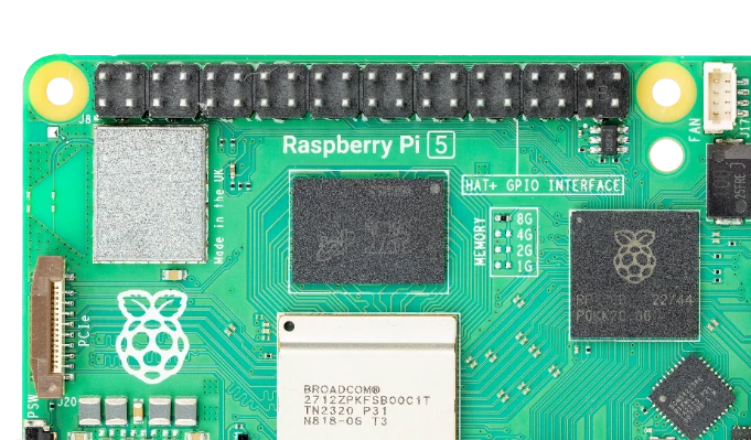
Raspberry Pi 5


The Raspberry Pi 5, like previous models since the Pi B+ and Pi 2, uses a 40-pin GPIO header. This keeps many HATs and expansion modules compatible. However, the Pi 5 does bring some technical improvements.
The header has a standard 2x20 pin layout: two rows of twenty. The pinout is largely the same as that of the Raspberry Pi 4. Under the hood, however, there are clear updates.
For example, a new I/O controller provides faster GPIO interfaces. The architecture of the Pi 5 has been revised, which improves support for UART, SPI and I2C. In addition, you can set additional functions per pin via software. This is done via so-called alternate functions (ALT modes).
The first two pins on the top left provide 3.3V and 5V power. After that comes a mix of GPIOs, ground pins, and communication pins. Think SDA/SCL (I2C), TX/RX (UART), and MOSI/MISO/SCLK/CE (SPI).
Please note: The physical layout is unchanged from previous 40-pin models. However, the functions of some pins may differ. So always check the official Raspberry Pi 5 pinout. You can also use tools such as pinout.xyz or the gpio readall command in the Raspberry Pi OS terminal.
In the rest of this article, we'll dive deeper into the functions of each pin, show you how to use them, and what to look for when connecting external components.
Raspberry Pi 2, 3 and 4 (40 pin)

The Raspberry Pi 2, 3 and 4 all use a 40-pin GPIO header. They share the same physical pinout. This allows you to use HATs and expansion boards on either model without any modifications. The underlying hardware is different, but the GPIO layout remains largely the same.
The 40 pins are divided over two rows of 20. They provide access to:
- Power pins: 5V on pins 2 and 4, 3.3V on pins 1 and 17, and multiple GND pins.
- Standard GPIOs: Freely programmable, usable as input or output.
- Communication protocols:
- I2C: pin 3 (SDA) and pin 5 (SCL)
- SPI: pin 19, 21, 23, 24 and 26
- UART: pin 8 (TXD) and pin 10 (RXD)
Some pins support alternate functions. Think of PWM for motors or GCLK for clock signals. You can set these functions via software.
A color-coded GPIO card is useful. It shows the function and the associated BCM number per pin. Most programming languages, such as Python with RPi.GPIO or gpiozero, use this BCM numbering.
Tip: Do you use multiple communication protocols at the same time? Then plan carefully which pins you use. This way you prevent conflicts between functions.
Since the pinout is standardized, you can easily switch between a Pi 2, 3 or 4. You don't have to change your hardware setup. Only for specific applications, such as SPI or UART performance, it is worth looking at the hardware differences.
Raspberry Pi Zero & Zero 2 W


The Raspberry Pi Zero and Zero 2 W are small, power-efficient and versatile. They have a full 40-pin GPIO header, allowing you to use the same accessories, HATs and expansion boards as larger models such as the Pi 3 and Pi 4.
The pinout layout is identical to that of the Pi 2, 3 and 4. So you have access to standard GPIO pins, power sources and communication protocols such as I2C, SPI and UART. PWM and clock signals are also available. With these you can control motors or LEDs, among other things.
There are a few things to keep in mind. Many Zero models are delivered without a soldered GPIO header. So you often have to solder the pins yourself to connect components.
In addition, the Pi Zero and Zero 2 W are less powerful than their bigger brothers. They have less RAM and processing power. This can play a role in projects that do a lot at the same time, such as controlling multiple sensors via I2C or SPI.
Yet these little Pis offer a surprising amount. They are ideal for projects that require little space or need to run for a long time on a battery. If you know their limitations and work with them, you can achieve a lot. Their simplicity and efficiency make them perfect for smart and lightweight applications.
Raspberry Pi 1 Model A (26 pin)


The very first Raspberry Pi , the Model A Rev 1.0, marks the beginning of the Raspberry Pi era. This compact model has a 26-pin GPIO header. Although you can do a lot with this, the layout and numbering differs from the later 40-pin versions. This makes it crucial to know exactly which pin is for what. The power pins provide 3.3V on pin 1, 5V on pins 2 and 4, and ground via pins 6, 9, 14, 20 and 25. These provide power or ground to connected components.
The GPIO pins use an older numbering than newer models. GPIO0 on pin 3 also functions as SDA for I2C. GPIO1 on pin 5 also functions as SCL. Other important pins are GPIO4 on pin 7 and GPIO14 and GPIO15 on pins 8 and 10. The latter two are used for UART communication, for sending and receiving respectively. Also, GPIO17 through GPIO25 can be found spread across pins 11 through 22 and pin 24. For SPI communication, GPIO10, GPIO9, GPIO11, GPIO8, and GPIO7 are important, each mapped to a specific pin from 19 through 26.
Please note that this version uses different GPIO numbers than later models. When writing or porting code, it is essential to take this into account. Some pins can support additional functions, such as PWM or clock signals. This depends on the software used and the specific model. Since this model is now outdated, documentation may be limited. Not all modern tools are fully compatible. Anyone working with this original Raspberry Pi should always keep an up-to-date pinout diagram at hand and be careful when connecting components.
Explanation of special connections
The Raspberry Pi GPIO header does more than just read or write digital signals. Some pins are intended for advanced communication. With these, you can control devices such as sensors, motor controllers and displays. These pins use protocols such as I2C, SPI and UART. Each protocol has its own advantages and applications. For example, you can exchange data quickly or connect multiple devices at the same time.
In addition to communication, you will also find pins for power supply. Some supply 3.3V or 5V, others serve as ground. With this you can supply power to connected components or connect them correctly. A number of pins support PWM, a technique with which you can imitate analog behavior. Think of dimming an LED or controlling a servo.
In the following chapters you will read how these connections work. You will also learn how to use them in your projects. This way you get the most out of the GPIO header and work safely with external hardware.
Input/Output
The most basic, but also most used function of GPIO pins is that of digital input or output. In this mode, pins can be programmed to read (input) or write (output) signals.
- Input : In this mode, a GPIO pin 'listens' for an electrical signal. For example, you can use this to read a button. When the button is pressed and voltage passes through, the signal on the pin changes from low (0) to high (1), or vice versa.
- Output : In this mode, the GPIO pin 'sends' a signal to a component. For example, think of controlling an LED, a relay or a buzzer. The pin then sets the signal to high (3.3V) or low (0V) to activate something.
The Raspberry Pi GPIO pins operate at 3.3 volts of logic , meaning a high output voltage is 3.3V. Caution : Applying 5V signals directly to a GPIO pin can permanently damage the Pi. In this case, use a voltage divider or logic level shifter.
Power pins (3.3V, 5V, GND)
In addition to the programmable GPIOs, the Raspberry Pi header also contains a number of dedicated power pins. These are intended to supply power to external components such as sensors, modules or microcontrollers.
- 3.3V pins
- Pins: 1 and 17
- These pins provide a constant 3.3V voltage directly from the Pi's voltage regulator. They are suitable for powering smaller 3.3V components.
- 5V pins
- Pins: 2 and 4
- These connect directly to the Pi's 5V power supply (via USB or GPIO power input) and can be used to drive more powerful modules that require 5V.
- GND (Ground)
- Multiple pins including 6, 9, 14, 20, 25, 30, 34 and 39
- Ground is the reference point for voltage and is essential in any electrical circuit. All connected components must be connected to at least one GND pin to function properly.
Correctly using the power pins is crucial for the stability of your project. Overloading the 3.3V regulator or shorting the 5V line can damage the Raspberry Pi .
I2C (SDA/SCL)
I2C (Inter-Integrated Circuit) is a serial communication standard. It allows multiple devices to connect using just two data lines with the Raspberry Pi . I2C is ideal for sensors, displays, and low-bandwidth chips.
The two lines are:
- SDA (Data) – Pin 3 (GPIO2)
- SCL (Clock) – Pin 5 (GPIO3)
These lines together form a bus. Both the Raspberry Pi and other devices are connected to this bus. Each device gets a unique address. This allows multiple components to work on the same two pins at the same time.
To use I2C, you need to enable it via raspi-config or config.txt . Pull-up resistors are needed — usually present on modules. If not, use e.g. 4.7kΩ to 3.3V.
Typical applications include:
- Temperature sensors (such as BMP280)
- OLED screens
- RTC clocks
- GPIO expanders (such as MCP23017)
SPI (MOSI/MISO/CLK/CE)
SPI (Serial Peripheral Interface) is a faster communication bus than I2C and is often used when speed or reliability is important. Unlike I2C, SPI requires more data lines.
The standard SPI bus on the Raspberry Pi consists of the following pins:
- MOSI (Master Out Slave In) – Pin 19 (GPIO10)
- MISO (Master In Slave Out) – Pin 21 (GPIO9)
- SCLK (Clock) – Pin 23 (GPIO11)
- CE0 (Chip Enable 0) – Pin 24 (GPIO8)
- CE1 (Chip Enable 1) – Pin 26 (GPIO7)
The Pi acts as a master and sends data via MOSI to the connected slave device. That device may send data back via MISO. CE0 and CE1 are used to indicate which device the Pi is currently communicating with (so you can connect multiple SPI devices as long as each uses its own CE pin).
SPI is ideally suited for applications such as:
- Fast ADC/DAC modules
- TFT and OLED screens
- SD cards
- RFID readers
As with I2C, SPI must first be enabled in the OS via raspi-config . It is also important to consider 3.3V logic on the Pi when connecting devices that operate at 5V.
UART (TX/RX)
UART (Universal Asynchronous Receiver/Transmitter) is a simple way to send data between two devices. Think of communication between a Raspberry Pi and a microcontroller, GPS module or sensor.
The Raspberry Pi has standard UART on these pins:
- TXD (transmit): Pin 8 (GPIO14)
- RXD (Receive): Pin 10 (GPIO15)
With UART, you use only two lines to send and receive data. Because the protocol is asynchronous, both devices must set the same baud rate. Common values are 9600 or 115200 bits per second.
Typical applications:
- Serial communication with Arduino or ESP32
- Debugging via a serial terminal
- Connect to GPS or GSM modules
By default, the Raspberry Pi uses UART for console signals. If you want to use UART for your own projects, you need to disable this feature via raspi-config or config.txt .
Pay attention to the voltage level. The Pi operates on 3.3V logic. Connecting a device that uses 5V can cause damage.
PWM (pulse width modulation)
PWM (Pulse Width Modulation) is a method of modulating a digital signal to behave like an analog signal. The Raspberry Pi doesn’t have built-in analog outputs, but with PWM you can still do things like:
- Dimming an LED steplessly
- Controlling the speed of a motor
- Controlling the position of a servo
By default, two pins are available on the GPIO header for hardware PWM:
- GPIO12 (PWM0) – Pin 32
- GPIO13 (PWM1) – Pin 33
(Alternatively GPIO18 and GPIO19 can also be used depending on the configuration)
PWM works by switching a digital pulse on and off at a certain frequency. The longer the signal is “high” relative to the time it is “low”, the higher the average power delivered. This is called the duty cycle .
For simple applications (like dimming an LED) you can also use software PWM via libraries like RPi.GPIO or gpiozero . For more precise timing, like with servo motors, hardware PWM is recommended.
Conclusion
The GPIO header is the beating heart of your Raspberry Pi projects. Beginner or advanced? Knowing the pinout is crucial. It will help you get the most out of your Pi.
In this article we will discuss the basics of GPIO. We will explain the differences between pinouts of various models. We will also discuss special connections such as I2C, SPI, UART and PWM. These make the Raspberry Pi a versatile controller.
Do you want to control an LED or read a sensor? Or connect a device via serial communication? With a good understanding of the GPIO pins you can work safely and efficiently.
Always use a current pinout diagram. Check that your components are suitable for 3.3V logic. This will prevent damage to your Pi.
With the right knowledge you build stable and smart solutions. And that gives long-term pleasure and success in your projects.